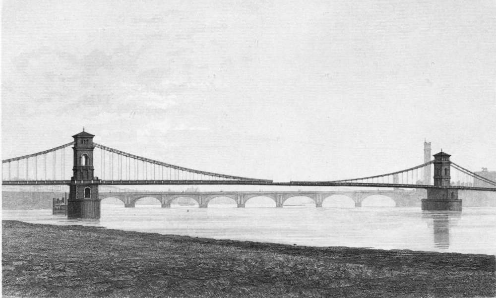
Hungerford Suspension Bridge (H. Adiard Sc.)
The suspension bridge which spanned the Thames at Charing Cross, on the site of the present railway bridge, was designed and constructed by Mr. Brunel between the years 1841 and 1845. It consisted of a centre span of 676 feet, and two side spans of 343 feet each. Being intended for foot passengers only, its width was 14 feet. The versed sine, or deflection of the middle of the catenary, was 50 feet. The two river piers, which still exist up to the level of the railway, and form piers of the present bridge, were of brickwork, with large footings at the bottom, so as to distribute the pressure over a considerable area. The whole structure was made hollow and as light as possible. From the level of the footway the piers were carried up as ornamental campanile towers, the weight of the chains being taken by four solid pillars of brickwork, 7 feet 3 inches square, forming the angles. Mr. Brunel introduced here many of the arrangements he had designed for the Clifton bridge. In order that the pressure from the chains might be always vertical on the piers, the saddles rested on rollers working in oil, on the level surface of a large cast-iron bed-plate. By this arrangement it was rendered possible for the chains of the land spans to leave the tower at a greater inclination than those of the middle span, so that the chains were made shorter, and as they were at a lower level where they met the abutment, there was less change in their direction at that point, and consequently less thrust on the brickwork. Freedom of horizontal motion was also secured, so that, in the case of unequal loading of the spans, the chains might accommodate themselves to the strains, and move horizontally until equilibrium was restored. At each of the land abutments the chains passed down over a fixed saddle, at an inclination, to anchorages placed at the bottom of the abutment. The brickwork under the fixed saddle was so disposed as to resist directly the thrust resulting from the change of direction between the main chains and the anchor chains. To resist any movement of the abutments, the piles on which they rested were driven obliquely, with their heads inclined from the river. These piles were very numerous, the abutments spreading out so as to cover a large area at the foundations. Nearly all the spaces between the longitudinal, cross, and outside walls were filled with concrete, in order that the abutments might be as massive as possible. The details of the brickwork in the piers and abutments showed Mr. Brunel’s skill in the economical employment of this material. The chains were constructed so that the sectional area was proportional to the strain; the total area at the centre was 296 square inches, while near the piers it was 312 square inches. There were four chains, two on each side of the bridge, placed one above the other, and consisting each alternately of ten and eleven links. The links were 24 feet long and 7 inches in depth, the thickness varying so as to give the requisite sectional area.
The relative diameter of pin, and proper form of the ends of the link, were subjects of much consideration, and many experiments were made in order to determine these points. The fact that two specimens of iron, apparently identical in every respect, sometimes exhibit considerable difference in their breaking weights, shows that an average of a great number of experiments is required in order to test satisfactorily any proposed refinements of construction. Mr. Brunel, however, convinced himself by experiment that he had practically arrived at such a form of link and diameter of pin that the chain would have no tendency to break at one point rather than another. The links were forged with shoulders near the eyes, in order that by means of clamps the pin could be taken out and the links disengaged, if necessary.
The efficient action of the rollers was demonstrated shortly after the completion of the bridge. On the occasion of the opening of the Corn Exchange by Prince Albert, one of the land spans was crowded with people, while the centre span was nearly empty. In consequence of this the land chains became depressed considerably below their normal position; and the saddles on the top of the tower nearest to the loaded span moved horizontally on the rollers to the extent of 3 inches; and, when the crowd had dispersed, they returned to their original position.
Many years after the completion of the bridge a proposal was made to widen it for carriage traffic; but this was not carried out, and eventually the superstructure was removed, to make way for the bridge of the Charing Cross Railway. As the Hungerford Suspension Bridge has ceased to exist, an engraving has been given of it (Plate II), in order that some record of its appearance may remain.
See also: Hungerford Bridge index entry